You have got a shiny new ESP32, an OLED display, a couple of sensors, and a relay module spread across your desk. The wiring diagram makes sense. The code compiles. But then you hit the question that stalls more beginners than any bug ever could:
"How do I actually power this thing?"
You are not alone. Power is the single most overlooked topic in electronics tutorials. Most guides hand-wave it with "connect 5V and GND" and move on. But get power wrong and nothing works -- or worse, you fry a component.
This guide will fix that. By the end, you will understand voltage, current, every common power source, how to regulate and protect your circuits, and how to confidently choose the right supply for any project.
Voltage and Current: The Two Numbers That Matter
Every power source is described by two values: voltage (V) and current (A).
Voltage is pressure. Think of it as the force pushing electrons through your circuit. A 5V supply pushes harder than a 3.3V supply, just like a tap at high pressure pushes water faster than a gentle trickle.
Current is flow. It measures how many electrons actually move through your circuit per second, measured in amps (A) or milliamps (mA). 1A = 1000mA.
Here is the critical insight beginners miss: your device draws the current it needs. A 5V/3A power supply connected to an ESP32 that only needs 200mA will deliver exactly 200mA. The "3A" is the maximum the supply can provide, not what it forces into your circuit.
Power (watts) ties them together:
Power (W) = Voltage (V) x Current (A)
A 12V LED strip drawing 2A consumes 24W. A 5V ESP32 drawing 0.2A consumes 1W. This matters when choosing your supply and calculating battery life.
Common Voltage Rails in Electronics
Not every device runs on the same voltage. Here are the standard "rails" you will encounter:
| Voltage | Common Uses |
|---|---|
| 3.3V | ESP32, ESP8266, most modern sensors (BME280, MPU6050), SD card modules, LoRa modules |
| 5V | Arduino Uno/Nano, WS2812B (NeoPixel) LEDs, servo motors, USB devices, relay modules, many LCD/OLED displays |
| 9V | Arduino barrel jack input, some sensor shields, legacy devices |
| 12V | LED strips (SMD 2835/5050), DC motors, cooling fans, solenoid valves, CCTV cameras |
| 24V | Industrial sensors, stepper motors (NEMA 17/23), larger LED installations, PLCs |
Many projects need multiple voltages. A typical home automation node might need 12V for a relay coil, 5V for an Arduino, and 3.3V for an ESP32 and sensors. That is completely normal -- you just need voltage regulators (covered below).
Power Sources Compared
| Source | Voltage | Typical Current | Best For | Limitations |
|---|---|---|---|---|
| USB-A (computer port) | 5V | 500mA | Flashing code, light testing | Low current ceiling |
| USB 3.0 port | 5V | 900mA | Slightly beefier testing | Still limited |
| USB-C with PD | 5-20V | Up to 5A (100W) | Raspberry Pi 5, laptops, fast charging | Needs PD negotiation IC |
| USB wall charger | 5V | 1-3A | Arduino, ESP32, small projects | Fixed 5V unless PD |
| AA batteries (x4) | 6V (4 x 1.5V) | ~500mA continuous | Remote sensors, portable projects | Voltage drops as they drain |
| 18650 Li-ion | 3.7V nominal | 2-3A continuous | Wearables, IoT nodes, flashlights | Needs charge protection circuit |
| LiPo battery | 3.7V nominal | High burst (10-50A for RC) | Drones, RC cars, high-current portable | Puffy = dangerous, needs careful handling |
| 9V battery | 9V | ~50mA usable | Quick Arduino testing | Terrible capacity (~500mAh), dies fast |
| 12V wall adapter (SMPS) | 12V | 1-5A typical | LED strips, motors, always-on projects | Mains-powered, not portable |
| Bench power supply | 0-30V adjustable | 0-5A+ adjustable | Development, testing, debugging | Expensive, not for final deployment |
USB Power: Know Your Ports
USB is the most common way beginners power projects, but not all USB is created equal.
USB-A (USB 2.0): 5V at 500mA maximum. This is your standard computer port. Enough for an Arduino Uno or a bare ESP32, but add a few sensors, an OLED, and some LEDs and you will hit the limit.
USB 3.0 (blue port): 5V at 900mA. A bit more headroom, but still just 5V.
USB-C with Power Delivery (PD): This is a game-changer. USB-C PD can negotiate voltages of 5V, 9V, 12V, 15V, or 20V at up to 5A (100W). The Raspberry Pi 5 uses USB-C PD for its 5V/5A requirement. To use non-5V voltages, your circuit needs a PD negotiation chip (like the FUSB302 or CH224K) to request the voltage it wants.
Quick rule: For projects drawing under 500mA at 5V, any USB port works. For 500mA-2A, use a USB wall charger rated for at least that current. For anything higher or needing non-5V, look at dedicated adapters or USB-C PD.
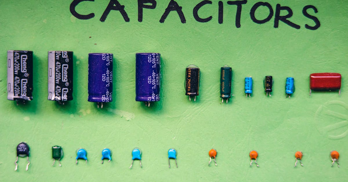
Battery Chemistry Cheat Sheet
Batteries are not interchangeable. Each chemistry has a different voltage, capacity, and behaviour.
| Battery | Chemistry | Nominal Voltage | Typical Capacity | Rechargeable | Notes |
|---|---|---|---|---|---|
| AA | Alkaline | 1.5V | 2000-3000mAh | No | Cheap, widely available. Voltage drops from 1.5V to ~0.9V as it drains. |
| AA | NiMH | 1.2V | 1900-2800mAh | Yes | Slightly lower voltage. Great for high-drain devices. Eneloop is the gold standard. |
| 18650 | Li-ion | 3.7V (range: 3.0-4.2V) | 2000-3500mAh | Yes | The workhorse of portable electronics. Used in laptop packs, power banks, torches. |
| LiPo pouch | Li-Polymer | 3.7V (range: 3.0-4.2V) | 100-10000mAh | Yes | Flat pouch cells. Higher discharge rates than 18650. Common in drones and RC. |
| CR2032 | Lithium | 3.0V | ~220mAh | No | Coin cell. For RTCs, key fobs, ultra-low-power sensors. Cannot supply more than ~15mA. |
| 9V block | Alkaline | 9V | ~500mAh | No | Convenient voltage but pathetic capacity. An Arduino with a few LEDs will drain it in hours. |
Series vs Parallel: Combining Batteries
Series (+ to -): Voltages add up, capacity stays the same.
2 x 18650 in series = 7.4V nominal, same mAh as one cell
3 x AA in series = 4.5V (alkaline) or 3.6V (NiMH)
Parallel (+ to +, - to -): Voltage stays the same, capacity adds up.
2 x 18650 in parallel = 3.7V nominal, double the mAh
Important: Only combine batteries of the same chemistry, same capacity, and ideally from the same batch. Mismatched cells cause imbalanced charging and can be dangerous, especially with lithium cells.
For lithium batteries, always use a Battery Management System (BMS) for charging, balancing, and over-discharge protection. A 2S BMS handles two cells in series. A 3S BMS handles three. Never charge bare lithium cells without protection.
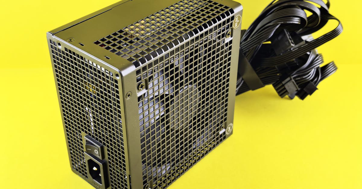
Wall Adapters and SMPS
For always-on projects (home automation hubs, security cameras, LED installations), wall adapters are the standard choice.
In India, mains power is 230V AC at 50Hz. A wall adapter (technically a Switch-Mode Power Supply or SMPS) converts this to low-voltage DC. Modern SMPS adapters are compact, efficient (85-92%), and relatively cheap.
Common configurations:
- 5V/3A (15W): Raspberry Pi, ESP32 projects, USB hubs
- 12V/1A (12W): Short LED strips (up to ~1 metre of 5050 LEDs), small DC motors
- 12V/2A (24W): Longer LED strips (2-3 metres), medium motors
- 12V/5A (60W): Full 5-metre LED strips, multiple motors
- 24V/2A (48W): Stepper motors, industrial sensors, longer LED runs
How to choose: Calculate the total current draw of your project (see "Current Budgeting" below), then pick an adapter with at least 20% more current capacity than your maximum draw.
Barrel jack polarity: Most adapters use a 5.5mm x 2.1mm barrel jack with centre-positive polarity (the inner pin is +, the outer ring is -). This is the standard for Arduino and most development boards. Always check before connecting -- a centre-negative adapter will damage your board.
Voltage Regulation: Getting the Right Voltage
Your power source rarely matches what your circuit needs exactly. A 12V adapter is useless to a 3.3V ESP32 without regulation.
Linear Regulators
Linear regulators are the simplest option. They work by burning off excess voltage as heat.
7805: The classic. Takes 7-35V input, outputs a steady 5V at up to 1A. Drop a 12V supply to 5V for an Arduino.
AMS1117-3.3: Takes 4.5-12V input, outputs 3.3V at up to 1A. The go-to for powering ESP32 and 3.3V sensors from a 5V rail.
The catch -- heat. A linear regulator wastes power equal to:
Power wasted = (Vin - Vout) x Current
Example: powering an ESP32 (3.3V, 300mA peak with Wi-Fi) from a 12V supply through an AMS1117:
Wasted = (12 - 3.3) x 0.3 = 2.61W
That is 2.61W of pure heat from a tiny chip. The regulator will get scorching hot and may shut down. Linear regulators work best when the voltage difference is small (7V to 5V, or 5V to 3.3V).
Switching Regulators (Buck Converters)
When the voltage gap is large or the current is high, use a switching regulator (buck converter). These chop the input voltage at high frequency and are 85-95% efficient.
LM2576: A classic buck converter. 7-40V input, adjustable output or fixed 3.3V/5V/12V, up to 3A. Through-hole, easy to use, but older and runs at 52kHz (needs larger inductors).
MP1584: A modern mini buck module. 4.5-28V input, adjustable output 0.8-20V, up to 3A. Tiny breakout boards available for under 50 rupees. Runs at higher frequency, smaller components.
When to use which:
| Scenario | Regulator | Why |
|---|---|---|
| 5V to 3.3V, under 500mA | AMS1117-3.3 (linear) | Small drop, simple, cheap, no noise |
| 7-9V to 5V, under 500mA | 7805 (linear) | Classic, reliable for Arduino |
| 12V to 5V, over 300mA | MP1584 or LM2576 (switching) | Too much heat for linear |
| 12V to 3.3V, any current | Switching only | 8.7V drop is way too much for linear |
| 24V to 5V | Switching only | Never use a linear regulator here |
| Battery-powered project | Switching only | Efficiency matters for battery life |
Powering Popular Dev Boards
Arduino Uno / Nano
Three ways to power an Arduino Uno:
- USB (5V): Powers the board directly. Limited to USB port current (500mA from a computer, more from a charger).
- Barrel jack (7-12V recommended): The onboard 5V linear regulator drops the input to 5V. Do not exceed 12V -- the heat dissipation gets excessive. 9V is the sweet spot.
- VIN pin (7-12V): Same as the barrel jack, just a pin header instead of a connector. Goes through the same onboard regulator.
Do not connect more than one power source simultaneously unless you know what you are doing. The USB port has a protection diode, but barrel jack + USB together can cause issues.
ESP32
The ESP32 draws up to 300-500mA during Wi-Fi transmission bursts, so it needs a solid supply.
- USB (5V): Through the micro-USB or USB-C port on the dev board. The onboard AMS1117 regulates to 3.3V. Use a quality cable -- thin cables cause voltage drops.
- VIN / 5V pin: Feed 5V directly to the 5V pin. This bypasses USB but still uses the onboard 3.3V regulator. Do not exceed 5.5V.
- 3.3V pin directly: If you have a regulated 3.3V supply, you can feed it directly to the 3.3V pin, bypassing all onboard regulators. Be precise -- the ESP32 tolerates 3.0-3.6V. Anything above 3.6V may damage it.
Common mistake: Trying to power an ESP32 from the 3.3V output of an Arduino. The Arduino's 3.3V pin can only supply about 50mA -- the ESP32 needs up to 500mA. This will cause brownouts, random reboots, and hours of frustrating debugging.
Current Budgeting: Will Your Supply Keep Up?
Before choosing a power supply, add up the current draw of every component.
Example project: ESP32-based weather station with OLED display and LED indicator.
| Component | Voltage | Typical Current | Peak Current |
|---|---|---|---|
| ESP32 (Wi-Fi active) | 3.3V | 80mA | 500mA |
| SSD1306 OLED (128x64) | 3.3V | 10mA | 20mA |
| BME280 sensor | 3.3V | 0.5mA | 1mA |
| Status LED | 3.3V | 10mA | 10mA |
| Total | 100.5mA | 531mA |
Now add 20% headroom to the peak:
531mA x 1.2 = 637mA --> round up to 700mA or 1A supply
A 5V/1A USB charger through the ESP32's onboard regulator handles this easily.
Another example: 12V LED strip project with Arduino control.
| Component | Voltage | Current |
|---|---|---|
| WS2812B strip (60 LEDs, full white) | 5V | 3.6A (60mA per LED x 60) |
| Arduino Nano | 5V | 50mA |
| Logic level shifter | 5V | 10mA |
| Total | 3.66A |
With 20% headroom: 3.66 x 1.2 = 4.4A -- you need at least a 5V/5A supply. A phone charger is absolutely not going to cut it here.
Protection Circuits: Do Not Skip These
A bare circuit with no protection is one reversed battery, one static shock, or one voltage spike away from being garbage. Here are the essentials.
Reverse Polarity Protection
If someone (you, at 2 AM) connects the power backwards, everything can die instantly.
Diode method (simple): Place a diode (1N5819 Schottky) in series with the positive rail. Current flows one way only. Downside: you lose about 0.3-0.5V across the diode.
P-MOSFET method (better): A P-channel MOSFET in the high side acts as a smart switch. When polarity is correct, it conducts with nearly zero voltage drop. When reversed, it blocks. The IRLML6402 is a popular choice.
Overcurrent Protection (Fuses)
A fuse blows when current exceeds its rating, breaking the circuit before damage occurs.
Use a resettable PTC fuse (polyfuse) for development -- it trips when current is too high and resets after cooling. A 500mA polyfuse on the power rail of an ESP32 project is cheap insurance.
For final installations, a standard blade fuse or glass fuse rated slightly above your maximum expected draw works well.
ESD and Voltage Spikes
TVS (Transient Voltage Suppressor) diodes clamp voltage spikes. Place a TVS diode across your power rails (e.g., SMBJ5.0A for a 5V rail). When voltage spikes above the rated level, the TVS conducts and absorbs the spike.
This matters especially for projects connected to long cables, motors, or anything outdoors where static and induced voltages are common.
Decoupling Capacitors: The Unsung Heroes
Every IC (microcontroller, sensor, regulator) needs decoupling capacitors close to its power pins. These are small capacitors that absorb tiny voltage fluctuations caused by the IC switching internally.
The rule: Place a 100nF (0.1uF) ceramic capacitor as close as physically possible to the VCC and GND pins of every IC on your board.
For the main power rail: Add a bulk electrolytic capacitor (10uF to 100uF) near where power enters your circuit. This handles larger, slower voltage dips.
Power input --> [100uF electrolytic] --> power rail --> [100nF ceramic near IC1]
                                                    --> [100nF ceramic near IC2]
                                                    --> [100nF ceramic near IC3]
What happens without them: Random resets, garbled sensor readings, I2C/SPI communication failures, Wi-Fi disconnections. If your ESP32 randomly reboots, missing decoupling caps near the power pins are the first thing to check.
Grounding: The Foundation Everything Sits On
Ground is not just "the negative wire." It is the reference point for every voltage in your circuit.
Common Ground
Every module, sensor, and power source in your project must share a common ground. This is the number-one wiring mistake beginners make. If your Arduino is powered from USB and your sensor is powered from a battery, the Arduino cannot read the sensor unless their grounds are connected.
Star Grounding
For sensitive circuits (audio, precision ADC), avoid daisy-chaining ground connections. Instead, run separate ground wires from each subsystem back to a single central point. This prevents current from one subsystem creating voltage differences in another subsystem's ground path.
Ground Loops
When two devices are connected by both a signal cable and mains earth, a ground loop can form. This causes hum in audio circuits and noise in sensor readings. The fix is usually to break the loop with an isolator (optocoupler for signals, isolated DC-DC converter for power).
For most hobby projects, a clean common ground is sufficient. Star grounding and loop-breaking become important when you scale up or work with audio and precision measurement.
Power Supply Selection Flowchart
Use this decision tree for your next project:
START
  |
  v
Is it portable / battery-powered?
  |                  |
  YES                NO
  |                  |
  v                  v
What voltage       What voltage
does it need?      does it need?
  |                  |
  v                  v
3.3V: Single       5V: USB charger
18650 + LDO        (5V/2A or 5V/3A)
  |                  |
5V: 18650 +        12V: 12V SMPS
boost converter    adapter (pick
  |                current rating
12V: 3S 18650      per budget calc)
pack + BMS           |
  |                24V: 24V SMPS
  v                adapter
Add BMS for          |
lithium cells        v
  |              Add voltage
  v              regulators for
Calculate        each rail your
battery life:    circuit needs
                   |
Capacity (mAh)     v
/ Average draw   Add protection:
(mA) = Hours     fuse, reverse
                 polarity diode,
                 TVS, decoupling
                 caps
Battery life formula:
Runtime (hours) = Battery capacity (mAh) / Average current draw (mA)
A 3000mAh 18650 powering an ESP32 in deep sleep (10uA average with periodic wake):
3000mAh / 0.01mA = 300,000 hours = ~34 years (theoretical)
Realistically, self-discharge and wake-up bursts reduce this, but you can still get months to years from a single cell with aggressive power management.
Quick Reference: Common Setups
Here are proven, tested power configurations for popular projects:
ESP32 IoT sensor node (portable): Single 18650 cell, TP4056 charge module, output to ESP32 VIN (3.7V works on many boards via onboard regulator). Deep sleep between readings.
Arduino + relay home automation (always-on): 12V/2A SMPS wall adapter. 12V to relay coil directly. 12V to 7805 or MP1584 buck converter for 5V Arduino power.
Raspberry Pi media server: Official 5V/3A USB-C power supply (5V/5A for Pi 5). Do not use random phone chargers -- the Pi is very sensitive to voltage drops under load.
5-metre WS2812B LED strip: 5V/10A SMPS (60 LEDs/m x 5m = 300 LEDs x 60mA = 18A theoretical max at full white brightness). Inject power at both ends of the strip to avoid voltage drop. Use a 5V/10A supply if you will never run full white; otherwise size up.
NEMA 17 stepper motor with A4988 driver: 12V/2A or 24V/1A SMPS depending on your stepper's voltage rating. Separate 5V rail for the Arduino (use a buck converter from the same 12V/24V supply, or a separate USB connection).
Final Checklist Before You Power Up
Before connecting power to any project, run through this:
- Voltage matches what your circuit expects (or you have the right regulator)
- Current capacity exceeds your maximum draw by at least 20%
- All modules share a common ground
- Polarity is correct (double-check with a multimeter)
- Decoupling caps are placed near every IC
- Fuse or polyfuse is on the main power rail
- No exposed connections that could short (use heat shrink, electrical tape, or a case)
- Lithium batteries have a BMS or protection circuit
- You have measured the supply voltage with a multimeter before connecting to your circuit
Power is the foundation of every electronics project. Get it right, and everything else becomes easier. Get it wrong, and no amount of perfect code will save you.
Take the time to understand your power needs, choose the right source, regulate it properly, and protect your circuit. Your components -- and your wallet -- will thank you.